|
I'm still very much digging the Zoom G5. It just needs a few mods to make it more gig-friendly. Or just plain old easier to use.
|

|
|
With the G5, you can arrange and use up to nine effects—eight regular effects and one Z-Pedal
effect. The display shows four of these effects at a time. By scrolling, you can move to different parts
of the effect chain and view effects that might have been hidden. Click the image so see a larger version.
|

|
You can tell if there are any effects blocks "off screen" by looking in the bottom corners of diplay panel 1 and 4. If there are hidden slots you will see a small triangle. Click the image so see a larger version.
If you've just changed to a new patch, or scrolled the display panels, you will also see small representations of how many effect slots are hidden in each direction. Click the image for a larger version.
|

|
There are two ways the stock G5 scrolls. In the row of buttons across the top of the G5 there are two SCROLL buttons. Pressing the left pointing button or right pointing button will scroll the display in that direction.
You can also press and hold footswitches 1 and 2 simultaneously to scroll to the left and press and hold footswitches 3 and 4 to scroll to the right.
|

|
Neither of the stock choices is convenient. We need a switch box that will put the functionality of the SCROLL buttons within easy reach of your feet.
The following steps show how to do these mods yourself.
|

|
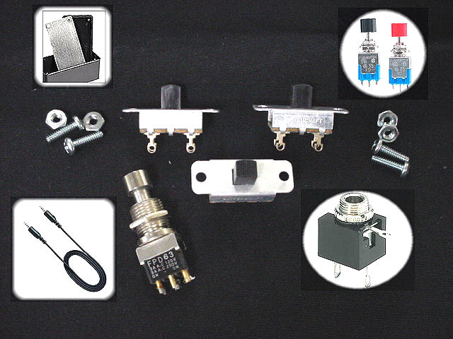
Here are the parts you'll need. The ones with a white background can be found at Radio Shack. The others are some that I've had lying around for a while. If you don't have extra parts lying around, this project can be completed using just the Radio Shack parts.
1/8" Stereo Panel-Mount Audio Jack (2-Pack)
Radio Shack search "1/8 cable stereo"
Radio Shack search "momentary switch"
Radio Shack search "project enclosure"
I found a cool jack that is insulated from whatever you mount it in and used these for my G5 project. They are larger than the Radio Shack jacks I've used before so I was unable to put a jack on each side of the switchbox. Instead, I put one jack in the middle.
|

|
|
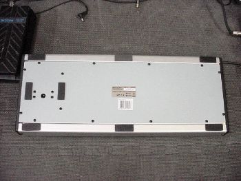
Remove the 18 screws from the bottom of the G5 and put them safely aside. Note that the 4 screws grouped together on the left side are not the same as the other 14. Keep those in a separate pile. Remove the back panel.
|
|
|
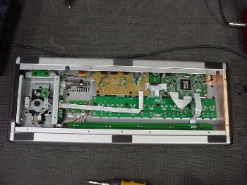
There is a green circuit board on the right that we will need to move so that we can access the circuit board beneath it.
|
|
|
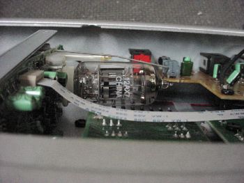
While we're in here, on the left you'll find the 12AX7 tube that drives the G5's Tube Boost feature. Click the image for a larger version.
|
|
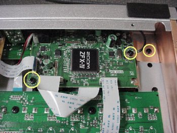
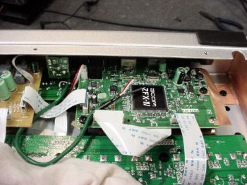
Unscrew the three screws circled in yellow. Zoom has used copper tape for shielding and ground in the top right. After removing the screws carefully pull up the strip of tape that is connected to the circuit board.
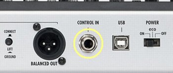
Unscrew the nut from the Control In jack on the rear panel.
|
|
|
Carefully pull the circuit board away from where it was connected before. Don't disconnect anything else. The space we have now with the board pulled back should be all that is needed.
|
|
|
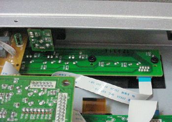
The dotted yellow circles show us where the solder spots are for the Scroll Left and Scroll Right buttons. Click the image for a larger version.
|

|
Solder the ends of three wires to the soldered spots as shown in the image. I used some extra pickup wire in the photo. I could have used three individual wires as well.
Here, the red/right wire is responsible for Scroll Left. The white/left wire is responsible for Scroll Right. The shield/middle wire is connected to a spot between the red wire and white wire spots. This middle spot is Ground and will be shared by the red and white wires in the new external switch box.
|

|
|
Put the circuit board back into the G5. Make sure that the wires you attached to the circuit board below this one are accessible after putting the board back in place. Screw in the two circuit board screws. Make sure to screw down the long black wire that came loose when we took out the screws earlier. The image does not show this wire. Then put the copper tape back to where it was and screw in the third screw. Screw the nut back onto the Control In jack on the rear panel.
|
|
Solder your wires to your jack. Solder the white/left wire to the 'tip' lug, the red/right wire to the 'ring' lug, and the shield/middle wire to the 'sleeve' lug.
Drill a hole in the rear panel of the G5 to seat your jack. In the photo the new jack on the right is the one I'm using for the Scroll Button mod.
Now let's make the switch box.
|

|
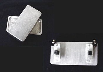
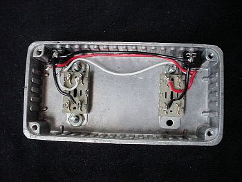
I had a small aluminum enclosures already so I used that. I laid out my controls where I wanted them and then put them into the box. I used two jacks in the photos below so that the box could be connected on either side of the G5 unit.
Click here to see how I wired a box with only one input jack.
|
|
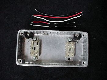
Now we're ready to wire up the box. For the jack inside the G5 I soldered the white/left wire to the 'tip' lug of the jack, red/right wire to the 'ring' lug of the jack, and the shield/middle wire to the 'sleeve' lug of the jack. Make sure that you use the same pattern when wiring the jacks inside the new box.
The momentary switches seen here have 4 terminals on them. The Radio Shack switches will typically have two or three. Two is all we need. The outer sets of terminals for each switch in the photo are not used.
|
|
|
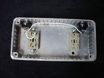
Each jack is sharing its connection with the other jack so first connect a long wire to the same lug on each jack. Here the white wire is soldered to the 'tip' lug of each jack. Then a smaller white wire gets connected to one of the terminals on the momentary switch.
|
|
|
Here the red wire is soldered to the 'ring' lug of each jack. Then a smaller red wire gets connected to one of the terminals on the momentary switch.
|

|
|
Here a black wire is soldered to the 'sleeve' lug of each jack. Then two smaller black wires get connected to the terminals across from the white and red terminals. When either button is pressed it will momentarily connect the red wire to the black wire or the white wire to the black wire, just like the little buttons at the top of the G5.
|
|
The finished switch box. I made the graphics in PowerPoint from images taken from the G5 manual. I printed them out on water-slide decal paper and a laser printer and put the decals on the boxes. I spray-painted some polyurethane on them for protection from scratches and rips in the decal.
[Box setup: 1- drilled the necessary holes. 2- put the decal on. 3- did the polyurethane. 4- put the jacks and switches in. 5- wired it up. 6- attached the bottom to the box.]
|

|
|
Here's my current set up after plugging a 1/8 stereo plug patch cable into the new jack on the rear panel of the G5 and the jack on the rear of the new Scroll Button switch box.
|

|
Take a picture of your modded setup and send it to ashbass to add it to the User Examples page.
|
|