-
PARTS: You'll need at least a double-pole double-throw (DPDT) stomp switch (a triple-pole double-throw (TPDT) will also work) , a soldering iron, and some solder.
|
-
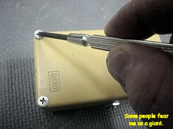
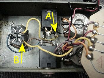
Open your pedal by taking out the four screws on the bottom. Remove the bottom cover and put it off to one side.
|
 |
-
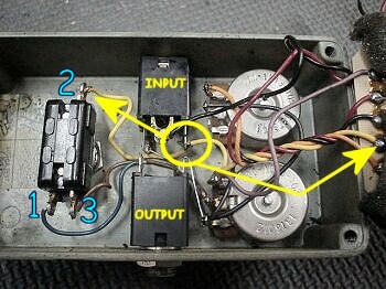
The blue numbers represent the legs on the switch. When 1 and 3 are combined, the effect is on as the brown wire from the volume pot is connected to the blue wire of the output jack. When 1 and 2 are combined, the effect is off as it is the yellow input wire that is connected to the blue wire of the output jack. But look to the right and you'll see that another yellow wire comes from the input jack and connects to the circuit board. This is how your input signal gets to the board even when 1 and 3 are combined. This is also the connection that must be fixed.
|
 |
-
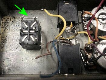
Remove the stock stomp switch and replace it with your new one. Solder a short piece of wire across the two poles at the end of the switch. It doesn't matter which end you do this on at this point.
|
 |
-
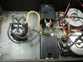
Solder the yellow input jack wire, the brown pot wire, and the blue output jack wire as shown in the photo. At this point, you have essentialy recreated the functionality of the original switch. You now need to address the problem of the 'loaded' yellow input wire.
|
 |
-
Break the connection between the input jack and the circuit board by unsoldering the yellow wire at point A in the photo. Then connect that wire to the remaining leg on the new switch (point B).
|
 |
-
You're all done.
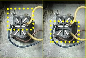
The left side photo shows the switch in bypass mode. Here the yellow input jack wire is connected to the blue output jack wire via the short jumper wire.
The right side photo shows the switch in active mode. Here the yellow input jack wire is connected to the yellow circuit boad wire to send the guitar signal into the effect. The brown pot wire is connected to the blue output jack wire thus completing the input=>circuit=>output chain.
|
 |