Epiphone valve junior modifications
What is it and what's wrong with it?
The epiphone valve junior is a very simple 5W tube combo with an 8”
speaker, tubes are one ECC83 (12AX7) and one EL84.
Its only features are an on/OFF switch and a volume control. It is
also very cheap, 115$ in the US or €150 in Belgium.
Some say it sounds very good, I think it needs major tweaking though.
The tweaking is necessary because of the noise and hum.
It hums quite loud when idle. When you turn up the volume there’s also a
higher pitched noise.
This makes the valve junior useless as a recording amplifier and
annoying for practice. Fortunately, solving this is not difficult.
Where does the noise come from?
The hum when idle is the result of a too low power supply capacitance.
The higher pitched noise is harder to trace. Part of it is that the
input is grounded through the chassis. Another problem begins in the
power transformer.
The high voltage power supply injects a lot of noise in the power
transformer, from loading the capacitors at each cycle.
The heater windings pick this up and spread this over the PCB. A better
layout would certainly help this.

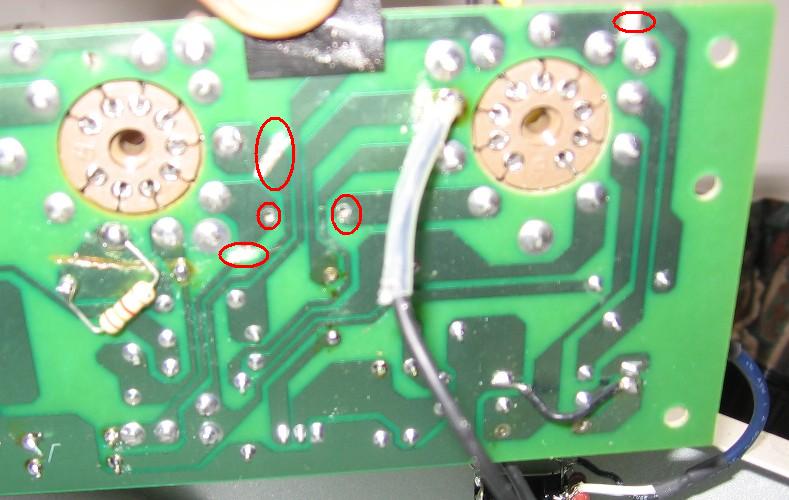
The layout problem is mainly in two places. At number one there is
Crosstalk between the heater and the trace from the volume pot wiper to
V1B. At number two there crosstalk between heater line
and the trace between anode of first gain stage to anode load resistor
(R3). I can't believe that they didn't discover this at epiphone. After
all, they should be the pro's.
There is also some crosstalk between heater and the trace between
anode of second gain stage to anode load resistor. On this location it
is less important though because the gain following this stage is low.
How can we solve this?
First of all the usual disclaimers: if you're not used to working with
high voltage electronics, don't open the amplifier but let a good tech
do the job.
The voltages inside the amplifier can kill you, even when the amplifier
is off and the power cord is disconnected. If you decide to open it, it
will void your warranty.
Do this at your own risk.
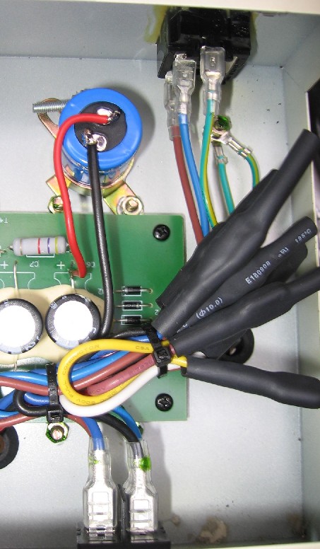
We have to do four things:
- grounding the input to the ground on the PCB and not the chassis.
-adding some capacitance in the power supply.
-Converting the heaters to DC or running them above the PCB.
-Running a shielded wire from the volume pot wiper to the Pin7 of the 12AX7.
Grounding the input properly is not so hard: replace the input jack
with an insulated one and add a jumper wire on the PCB. While at it we
can also remove R1
and replace it with a 1M resistor. This increases the input impedance
of the amplifier.
Adding some capacitance is easy too. I added a 100µF/450V capacitor
parallel with C6. This doesn't remove the hum completely, but is good
enough for me. You can add more capacitance for an even better result.
Some people decided to feed the heaters with a DC supply, which removes
a lot of garbage coming out of the power transformer.
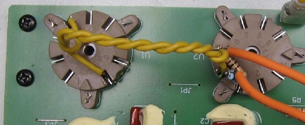
I tried this and this proved to be a good solution. I did not like the
idea though because the resulting voltage in my amplifier was only 5.8V
DC. So I cut some traces, removed jumper 1 and put the heater wiring
above the PCB.
I also referenced the heaters to the cathode of the EL84 with the
100ohm resistors R10 and R11. On the PCB I replaced them with jumper
wires.
If you like the idea of converting to DC better, check out the links at
the bottom of the page.
If you have any questions or remarks, you can mail me or post a message on the ampage BBS.
Links
Here are some links to other sites who explain mods to the valve junior:
http://www.euthymia.org/DIY/VJmods.html
http://www.coolpick.com/way/cool/about/valvejunior.html
 svokke@yahoo.com