An L-pad is a passive device which lets you control the output level of
speakers without changing the impedance seen by the amplifier. A
constant impedance is not really necessary for the amplifier but if you
are using passive crossovers, a constant impedance is necessary to
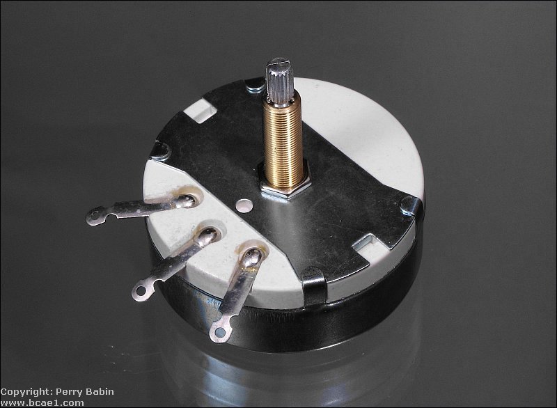
prevent the crossover frequency from changing. The following image shows
what typical L-pad looks like. This L-pad is relatively large (~3" in
diameter) because it's rated at 100 watts. L-pads rated for higher power
have to be larger than ones rated for lower power because they have to
dissipate more heat. This one has an unusually long shaft. This would
generally be installed directly into the wall of the speaker enclosure.
If you were using a terminal cup, you could use this (using nuts to
allow only a fraction of the shaft to protrude through the terminal cup
but it would be better to use one with a proper/short shaft.
Construction:
An L-pad consists of 2 resistors connected by a movable terminal (the
'wiper'). One resistor is in series with the load and the other (shunt)
resistor is connected in parallel with the load. The combination of the
series resistance and the parallel shunt/speaker loads will always
present a constant load to the amplifier. The diagram below shows the
schematic symbol for an L-pad. You can also see that the 2 resistors are
not the same value. The movable terminals vary the resistance in series
with the speaker and also vary the resistance in parallel with the
speaker load. The position of the wiper is determined by the position of
the volume knob on the L-pad.
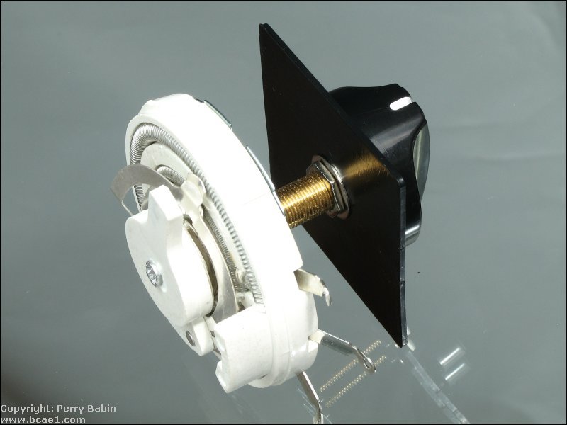
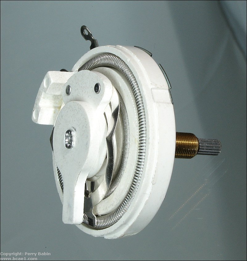
The following image shows the internal resistors and the wiper contact on the larger wirewound resistive element.
Connection:
An L-pad will generally have 3 or 4 terminals. For the ones with 4
terminals, two terminals are provided for the negative (one for the amp
connection and one for the speaker connection). The amplifier's speaker
output terminals are connected to the outer terminals of the L-pad. The
speaker's positive terminal is connected to the wiper. The speaker's
negative wire is connected to the same terminal as the amplifier's
negative speaker terminal.
Level control:
This diagram shows how the output level corresponds to the wiper
position. You can see that when the wiper is closer to the amplifier
positive out terminal, the output is greater than when the wiper is
close to the amplifier's negative output terminal. With the L-pad in the
fully clockwise position, the wiper is directly connected to the
positive terminal of the amplifier and there is no connection to the
shunt resistor. When the L-pad is in the fully counter-clockwise
position, the wiper (remember it's connected to the speaker's positive
terminal) is connected directly to the negative terminal which means
that the speaker can produce absolutely no output.
How does it do it?
The table below shows how the shunt and series resistances (in
conjunction with the speaker) maintain a constant load even though the
power getting to the speaker is not constant. The table shows the values
of the resistors starting at the maximum level (at the top) and ending
with zero volume.
Speaker load
Series resistance
Speaker and shunt in parallel
Shunt value
Load presented to amplifier
8 ohms
0 ohms
8 ohms
open
8 ohms
8 ohms
.5 ohms
7.5 ohms
120 ohms
8 ohms
8 ohms
2 ohms
6 ohms
24 ohms
8 ohms
8 ohms
3.5 ohms
4.5 ohms
10.29 ohms
8 ohms
8 ohms
5 ohms
3 ohms
4.8 ohms
8 ohms
8 ohms
6.5 ohms
1.5 ohms
1.85 ohms
8 ohms
8 ohms
8 ohms
0 ohms
0 ohms
8 ohms
The calculator below will allow you to calculate the series and shunt
resistors as well as the power rating for the respective resistors.
Don't try to find resistors with the same exact power rating as the
calculator recommends. Those values are the minimum safe value with the
given amplifier power. Use the next higher available power rating. The
terms 'shunt resistor' and 'parallel resistor' are interchangeable.
Don't let it confuse you.
Notes:
The voltage across the series resistor plus the voltage across the shunt/speaker combination must equal the total voltage from the amplifier's output.
The current through the series resistor is equal to the current from the amplifier's output.
The current through the shunt plus the current through the speaker must equal the total current from the amplifier's output.
The power dissipated in the speaker plus the power dissipated in the shunt resistor plus the power dissipated in the series resistor must equal the amplifier power.
The combination shunt/speaker impedance plus the series resistance must
equal the speaker's impedance. Remember that we're trying to reduce the
output of the speaker without changing the impedance seen by the
amplifier or passive crossover.
This
site introduces you to macro photography. Macro photography is nothing
more than the photography of small objects. It can take quite a while to
understand the limitations associated with this type of photography.
Without help, people will struggle to get good images. Understanding
what's possible and what's not possible makes the task much easier. If
you need to photograph relatively small objects (6" in height/width down
to a few thousandths of an inch), this site will help.
If
you're interested in air rifles, this site will introduce you to the
types of rifles available and many of the things you'll need to know to
shoot accurately. It also touches on field target competition. There are
links to some of the better sites and forums as well as a collection of
interactive demos.
This
site helps anyone new to computers and anyone with a basic
understanding of computers with a desire to learn more about the
internal components of a computer. If you have a computer that you'd
like to upgrade but don't know where to start, this is a good site for
you.
This
site is for those who want to begin racing karts but don't fully
understand how the various parts work. It's mostly interactive demos
that show how the various parts of the kart work.
Click HERE to visit a friend's new car audio tech site.


 An L-pad is a passive device which lets you control the output level of
speakers without changing the impedance seen by the amplifier. A
constant impedance is not really necessary for the amplifier but if you
are using passive crossovers, a constant impedance is necessary to
prevent the crossover frequency from changing. The following image shows
what typical L-pad looks like. This L-pad is relatively large (~3" in
diameter) because it's rated at 100 watts. L-pads rated for higher power
have to be larger than ones rated for lower power because they have to
dissipate more heat. This one has an unusually long shaft. This would
generally be installed directly into the wall of the speaker enclosure.
If you were using a terminal cup, you could use this (using nuts to
allow only a fraction of the shaft to protrude through the terminal cup
but it would be better to use one with a proper/short shaft.
An L-pad is a passive device which lets you control the output level of
speakers without changing the impedance seen by the amplifier. A
constant impedance is not really necessary for the amplifier but if you
are using passive crossovers, a constant impedance is necessary to
prevent the crossover frequency from changing. The following image shows
what typical L-pad looks like. This L-pad is relatively large (~3" in
diameter) because it's rated at 100 watts. L-pads rated for higher power
have to be larger than ones rated for lower power because they have to
dissipate more heat. This one has an unusually long shaft. This would
generally be installed directly into the wall of the speaker enclosure.
If you were using a terminal cup, you could use this (using nuts to
allow only a fraction of the shaft to protrude through the terminal cup
but it would be better to use one with a proper/short shaft.